This white paper will discuss some methods of selecting the best Stepper Drive for motion control applications requiring a Stepper Motor or a Stepper-Based Linear Actuator; information about the typical types of Stepper Drives; the effects of different applied voltage levels; and of various drive settings and options for operating these motors.
Stepper Motors and Stepper-Based Linear Actuators are often selected for open-loop motion control devices and equipment. These can be found in a wide range of products and systems such as: laboratory equipment, medical devices, vision systems, analytical equipment, office products, semiconductor equipment, aerospace, communications systems and light industrial equipment.
 Two Basic Types of Stepper Drives
The two major types of Drives for Stepper Motors and Stepper- Based Linear Actuators are the L/R Drive and the Chopper Drive. Some of the criteria for choosing the Drive type include:
- Cost of the drive
- Physical size and configuration of the drive
- Available power source
- Rated output current of the drive
- Motion duty cycle
- Total loading on the motor
- Required speed range of the motor
|
The L/R Drive
Think of this type as a “constant voltage” Drive. For continuous duty motor operation in a room temperature environment you essentially match up the available power source voltage for the
L/R Drive to the rated coil voltage of the motor. Regarding the name L/R Drive - the “L” is the electrical symbol for Inductance and the “R” is the electrical symbol for Resistance. Since the Stepper Motor torque is proportional to ampere-turns it is the current through the motor windings that determines the output performance at any speed including zero.
At standstill the maximum “Holding Current” current through the windings is limited by the coil resistance. As the stepping rate (motor speed) increases, the coil inductance becomes a major current limiting factor (limiting the rate of change of coil current) along with the Back-emf. Back-emf is a generated voltage proportional to the speed that is produced within the motor windings during rotation which works against the source voltage, because every motor is also a generator.
The motors operated with an L/R Drive will have a relatively limited performance range when compared to using a Chopper Drive. The source-voltage-to-motor-voltage ratio with the L/R Drives is basically 1:1 whereas with Chopper Drives it can be many multiples such as 2:1, 4:1, 8:1, or more. Refer to Figure 3.
Some of the reasons for selecting an L/R Drive instead of a Chopper Drive might be a lower cost of the Drive, smaller physical size of the Drive, a relatively slow motor speed range, use of a Unipolar motor or the limitations of using a battery power source. A good example of a product utilizing many of these previously listed reasons for using an L/R Drive with a small Stepper-Based Linear Actuator is a Handheld Electronic Pipette. See Figure 1.
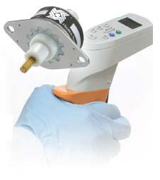 |
Figure 1: Can-stack linear stepper motors such as the Haydon Kerk Z26000 Series are used in a wide variety of medical applications including motorized handheld pipettes.
|
Typically, L/R Driven performance curves published by Stepper Motor and Stepper-Based Linear Actuator manufacturers were developed with the full rated motor voltage available at the motor’s lead wires at zero steps per second. If there are any voltage drops through the Drive circuitry then this DC Power Supply voltage would be set slightly higher to compensate for the total voltage loss in the Drive.
The CHOPPER Drive
Think of this type as a “constant current” Drive. For continuous duty motor operation in a room temperature environment you set the output RMS (Root Mean Square) current of the Chopper Drive to the rated RMS coil current of the motor. Regarding the name Chopper Drive, this technique for maintaining the proper motor phase current levels throughout a usable speed range is to rapidly turn on and off (i.e., ‘chopping’) a relatively high source voltage via a proportional duty cycle while circuitry monitors the current levels in the motor windings. Chopper Drives can be separate ‘standalone’ units or integrated with the motor. For one example of a compact ‘stand-alone’ Chopper Drive see Figure 2.
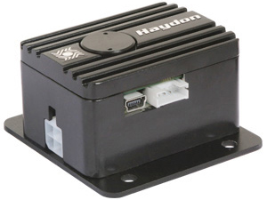 |
Figure 2: PC programmable PCM4806E Idea Drive
|
If the application has a fairly short duty cycle (i.e., the ‘full powered’ ON or ‘Run’ times relative to the OFF or lower-current zero motion ‘Hold’ times) in a moderate temperature environment, then a higher magnitude of ‘Run’ current can be used to increase the motion performance of the motor. However, care must be taken when using this higher than rated ‘Run’ current. The current levels and ON times versus ‘Hold’ or OFF times, as well as the ambient temperature, and any motor cooling methods (conduction, convection, etc.,) will determine the internal coil temperatures. It is recommended to consult the motor manufacturer if significantly high phase currents are necessary.
The additional circuitry within Chopper Drives sense the magnitude of the phase currents, and to control the voltage ‘chopping’ may increase their price (compared to an L/R Drive), but it can help to maintain a high level of motor torque or force throughout a relatively wider speed range. The power supply voltage to a Chopper Drive is typically much higher than the rated voltage of the motor. As discussed in the L/R Drive section above the source-voltage to motor-voltage ratio for a Chopper Drive is usually significantly higher than 1:1 and is typically 8:1 or even higher. Therefore the relative performance range can be greatly improved. Refer to Figure 3.
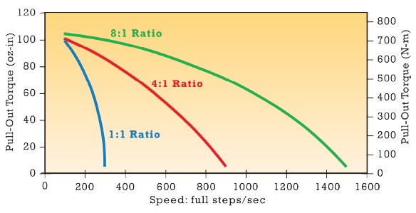 |
Figure 3: Relative effect of the source-to-voltage ratio on motor performance.
|
The inductance of relatively low voltage Stepper Motors and Actuators is significantly less than their mechanically equivalent motors of higher rated coil voltages. For very good motor performance over a wider speed range, a low voltage motor operated with a Chopper Drive at a relatively high source voltage is selected. The relatively low inductance and lower Back-emf characteristics of a low voltage motor in conjunction with a high source voltage Chopper Drive can provide excellent performance results. The major requirement with these low voltage motor configurations is that the Drive has to be capable of providing higher levels of phase current.
As a cautionary note, some Chopper Drive manufacturers advertise their product’s output phase current levels as a peak value, using larger values is typically a marketing tactic. However, the continuous duty phase currents for Stepper Motors and Stepper-Based Linear Actuators are typically rated as RMS (Root Mean Square) values. The conversion: RMS = Peak x 0.707
There can be other configurations and features for Stepper Drives:
• Bipolar Drives
For operating 4 or 8 lead bipolar Stepper Motors and Stepper-Based Linear Actuators
• Unipolar Drives
For operating 6 or 8 lead unipolar Steppers and Actuators (typically L/R type Drives).
• Non-programmable Drives
Requiring digital “Pulse” and “Direction” inputs from a controller (and some include an “Output Enable” digital input). The controller outputs a single pulse to the Drive for each motor step and outputs a stream of pulses to the Drive for the motor to ‘Index’ a precise amount. The quantity of pulses to the Drive determines the amount of rotational or linear movement and the frequency of the pulse train determines the rotational or linear speed of the Stepper Motor or Linear Actuator respectively.
• Programmable Drives
These drives incorporate a microprocessor and can execute various motion control programs in addition to immediately executable motor commands. These Drives can have the motor ‘Index’ virtually any amount in either direction and at various speeds in real time or under user-specified program control. Most programmable Drives have some General Purpose (GP), digital Inputs/Outputs (I/O) for ‘talking’ with or controlling other equipment (and thus providing coordinated system motion control), and also have some conditional functions based upon the GP Inputs, the relative motor position, and/or encoder feedback data.
• Half Step Mode in addition to standard Full Step Mode
In the Half Step Mode, the Drive can electronically divide each full step of a Stepper Motor in half. For example, a Stepper Motor with a 15° full step rotation can operate at a 7.5° step angle with the Drive in the Half Step Mode. A 1.8° Stepper Motor can be run with 0.9° half step increments, and so forth. Similarly the linear resolution of a Stepper-Based Linear Actuator can be divided in half using the Half Step Mode.
• Micro-Stepping Modes
Micro-Stepping Drives can electronically divide each full step of a Stepper Motor or Actuator into finer discrete step angles than Half Stepping. Typical division factors are 1/4, 1/8, 1/16, 1/32, etc, and/or 1/5, 1/10, 1/25, 1/50, etc. The four major benefits of micro-stepping the motor are increased rotary or linear resolution, smoother operation, reduced audible dynamic noise and a reduction of dynamic resonance. The trade-off for these benefits is a reduction in motor step accuracy and repeatability, especially under loaded conditions.
• Encoder Input
There are many applications which may require a method of speed verification and/or positional verification such as certain medical devices, gases or liquids flow regulation, communications equipment or microelectronics. To ‘close-the-loop’ of a Stepper-Based system an integrated motor-mounted or a load-attached rotary or linear Encoder can essentially ‘tell’ this type of Drive if the motor is successfully achieving the commanded step rates and/or has achieved the true commanded position for every move. An Encoder can also recover the significant loss of motor step accuracy when using fine micro-stepping modes as described above.
• Acceleration and deceleration ramping
To help get a relatively greater load moving and/or achieve higher motor step rates (possibly without having to change to a physically larger motor), the use of accel/decel ramping can often be implemented with many Stepper Drives. As shown in typical published (non-ramped) speed, versus torque or speed versus force performance curves for Stepper Motors or Stepper-Based Actuators, the slower the motor speed the higher the output torque or output force respectively. See Figure 4 for an example of a Linear Actuator non-ramped performance curve.
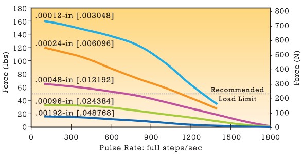 |
| Figure 4: Non-ramped performance curve for Size 17 bipolar, hybrid linear stepper motor with 100% duty cycle chopper drive. |
To benefit from ‘lower speed, higher force levels’ the rotary or linear move profiles can include an initial start, from standstill, at a relatively low base speed and then immediately begin ramping up to the desired ‘high velocity’, and to then reverse this technique if a deceleration ramp is also required.
Just as we have to accelerate heavy motor vehicles up to speed from a dead stop, Stepper Motors and Actuators can usually get relatively large loads moving with the use of ramping. To continue with this analogy, it requires extra power (i.e. engine mechanical horsepower for a conventional vehicle or electrical power for a
motor) to get moving up to speed and then, depending upon the type of loading, it may take significantly less power to maintain motion at a constant velocity. Refer to Figure 5 for an example of a possible performance benefit with ramping.
• A phase current ‘boost’ feature
Some Chopper Drives offer an option to set a boosted phase current (higher magnitude than continuous rated current) during part of, or possibly all of, any acceleration and/or deceleration ramp. Typically the ‘active time’ of boosted current levels are of limited duration during a ramp to prevent overheating the motor windings. This boosted current during an acceleration ramp can increase the internal torque of the motor allowing the motor to get a relatively larger load moving from the rest position. Similarly a boosted current during a deceleration ramp can help to stop a relatively larger moving load.
 |
Fig. 5: Linear actuator performance with and without ramping.
|
In Summary
There may be many factors to consider when designing a motion control device or system using Stepper Motors or Stepper-Based Linear Actuators. One of the critical components is the Stepper Drive and its selection is best determined by various factors such as the type, physical size, voltage and current ratings, available step modes,
controllability and programmability, ramping and/or current boosting options, as well as cost and delivery lead time. Depending upon the loading and duty cycle significantly improved performance from, or the increase in energy efficiency of a Stepper Motor or Stepper-Based Actuator can often be achieved by the proper selection of the Drive type (along with any optional features of the Drive) and the power source.
FAQ
1. What is a stepper drive?
A stepper drive is an electronic device that controls the current and voltage supplied to a stepper motor. The drive interprets control signals and precisely energizes the motor windings to achieve accurate positioning, speed control, and motion performance.
2. How do I select the proper stepper drive?
Selecting the proper stepper drive requires evaluating motor voltage, current requirements, speed range, load characteristics, available power supply, and control requirements. The drive should be matched to the motor and application to achieve the desired performance and reliability.
3. What is the difference between an L/R drive and a chopper drive?
An L/R drive operates as a constant-voltage drive and is typically used in lower-speed applications. A chopper drive operates as a constant-current drive and provides improved torque performance over a wider speed range through high-frequency current regulation.
4. When should I use a chopper drive?
Chopper drives are commonly used when applications require higher speeds, improved torque performance, microstepping capability, or wider operating ranges. They are often preferred for demanding motion control systems that require maximum efficiency and flexibility.
5. Why is drive voltage important for stepper motor performance?
Drive voltage affects how quickly current can build within the motor windings. Higher voltages, when used with appropriate current control, can improve high-speed torque and overall motion performance while maintaining motor protection.
6. How does current affect stepper motor performance?
Stepper motor torque is directly related to winding current. Proper current settings help maximize torque output while preventing excessive heat generation. Incorrect current settings can lead to reduced performance or shortened motor life.
7. What is microstepping in a stepper drive?
Microstepping is a control technique that divides a motor's full step into smaller increments. This can improve motion smoothness, reduce vibration, decrease audible noise, and increase positioning resolution in many applications.
8. Does microstepping increase accuracy?
Microstepping increases positioning resolution and can improve motion smoothness. However, actual positioning accuracy depends on factors such as motor design, load conditions, system mechanics, and drive quality.
9. What are the benefits of acceleration and deceleration ramping?
Acceleration and deceleration ramps help start and stop loads more smoothly by gradually changing motor speed. Ramping can improve reliability, reduce the risk of missed steps, and allow the motor to handle larger loads more effectively.
10. What is the role of an encoder in a stepper motor system?
An encoder provides feedback about motor position or speed. When integrated into a motion control system, encoder feedback can improve positioning verification, system monitoring, and overall performance in demanding applications.
11. Can a stepper motor operate without feedback?
Yes. Most stepper motor systems operate in open-loop mode without feedback devices. In applications requiring position verification or enhanced system monitoring, encoders may be added to provide feedback.
12. What factors influence stepper motor torque?
Stepper motor torque is influenced by drive current, applied voltage, motor design, operating speed, load conditions, acceleration requirements, and drive configuration. Proper motor and drive matching helps maximize usable torque.
13. How do I improve stepper motor speed performance?
Speed performance can often be improved through proper drive selection, optimized voltage levels, current regulation, acceleration ramping, and selecting a motor designed for the required operating range.
14. What is the difference between full-step, half-step, and microstep operation?
Full-step operation advances the motor by one complete step at a time. Half-step mode divides each full step into two increments. Microstepping further divides each step into smaller increments, improving smoothness and positioning resolution.
15. How do stepper drives affect energy efficiency?
Modern stepper drives can improve energy efficiency through current regulation, programmable operating modes, reduced idle current settings, and optimized motion profiles. Proper drive selection can help reduce power consumption while maintaining motion performance.
16. How do I select the proper stepper motor for my application?
Evaluate torque requirements, speed, positioning accuracy, duty cycle, load characteristics, and available power. The motor should then be matched with a compatible drive to ensure optimal performance and reliability.
17. What size stepper motor do I need?
The appropriate motor size depends on the required torque, speed, acceleration, and load conditions. Engineers typically use torque calculations and performance curves to determine the optimal motor size.
18. Why is matching the stepper motor and drive important?
The motor and drive work together as a system. Proper matching ensures efficient operation, maximizes torque output, improves speed capability, and helps prevent overheating or missed steps.
19. What is the best drive for a linear stepper actuator?
The best drive depends on the actuator's force requirements, speed range, power supply, and control needs. Chopper drives are often selected when higher performance across a wider operating range is needed.
20. Can the wrong drive reduce stepper motor performance?
Yes. An improperly matched drive can limit torque, reduce speed capability, increase heat generation, and decrease overall system efficiency.
Click here to download PDF version.